If you experimented with embedded devices like a Raspberry Pi or had a failed OpenWrt router firmware update, you know the drill: connect a USB-Serial TTL adapter to the three magic pins on the motherboard, labeled RX, TX and GND.
This opens up the gates to a new, otherwise undiscovered universe — the world of early stage bootloaders, built-in diagnostics, low-level recovery, etc. There is a good reason this is not exposed to the average customer: this domain is not for them. It’s a dangerous place, one can do serious damage when let loose.
But we’re no average customers, are we? No, we unironically keep a strand of unprotected Dupont-style breadboard jumper cables connected to these three UART TTL pins, dangling out through a little hole we drilled in the device enclosure. Because — duh — you never know when you’re going to need to connect to them again, right?
This is not only unseemly, it is also neither reliable nor safe. These wires are not meant to be bent often, which I learned the hard way in the case of my trusty NanoPi R4S, which would no longer accept inputs.
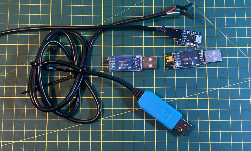
Also what do you connect the jumper cable to? Normally a USB-TTL adapter, which either comes in the cheap short and PCB-only shape or in the “keep me directly connected even if you stumble over my long cable” variant, and either way, you keep them connected because — duh — you don’t want to unnecessarily strain the Dupont wires…
Neither solution is appealing: you shouldn’t keep something permanently connected unless necessary (from my own experience, the USB adapters get back-fed some current from the RX/GND pins even when not connected on the USB end), and you shouldn’t keep a rather unprotected PCB hanging from three tiny wires. We can do better than that!
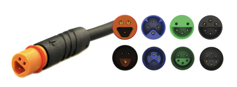
I have now found my favorite solution to the problem, and I’m therefore proposing a new standard (obligatory xkcd 927 reference), which hopefully catches on: Julet connectors.
These sturdy connectors are typically used on E-Bikes, and are actually already being used for serial TTL (to configure the e-bike controller, trip computer, etc.), along with carrying 48V!
Julet cables can readily be found on places like AliExpress, commonly in sizes M6 and M8, although other sizes are available. AliExpress Wiki has a good overview page.
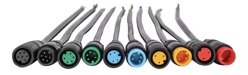
In a sense, they remind me of “PS/2” Mini-DIN. I guess what’s old is new. The Julet connectors come in many varieties, both in pin count, size and even shape (see the manufacturer catalog).
I’ve opted for the M6 variant, mostly because they are relatively small, cheap and readily available. The ones I ordered were actually made by yczxf; also note the similar HiGo connectors.
The yczxf cables are rated for 3A 0-24V DC and IP68, which is nice.
What is convenient is that these connectors come in ready-made 20cm pigtails, with pre-tinned wires ready for crimping, which means fully-working adapter cables can be made in a matter of minutes. For that I used the PEBA crimping pliers/Dupont/JST-XH connector toolkit available on Amazon. AliExpress also has full extension cables up to 1m long, for what it’s worth.
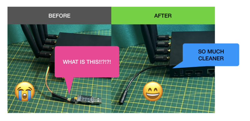
I found it effective (and inexpensive) to use zip ties around the cable as strain relief inside the enclosure, and optionally outside as well.
The setup is very robust and foolproof — no polarity guessing: simple plug and play.
This extends to the assembly phase, if you follow my suggestions:
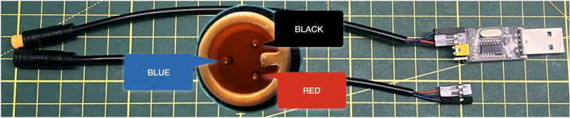
In my three-pin setup, the pigtails came with wires in three colors: blue, black and red. The black and red ones correspond to the pins next to the notch (see the picture above), which is why I assign them to RX and TX, leaving the blue wire for GND (ground).
The 2-pin dupont plastic header housings in my crimping toolkit came with an embossed arrow. By my convention, this indicates the receiving pin (RX). For TTL serial communication, RX and TX must be crossed, therefore I follow this practice: Female Julet connectors (sockets), which I use on the device-end, have the red wire with the arrow. Male Julet connectors (plugs), which I use on the USB-TTL side, have the black wire with the arrow.
The ground pin (blue wire) is carried on a separate, 1-pin Dupont header. This is allows for easy switching of the RX/TX orientation without having to disassemble the plastic housing, and also makes it easier to fumble pre-assembled cables through small holes than with a single three-pin Dupont header.
For future expansion: the 5-pin (green) and 6-pin (black) Julet sockets are compatible with the 3-pin plug, which means we can have a device expose additional (passive-wire) functionality with backwards compatibility for simple USB-TTL adapters. The colors of the wires in these variants differ slightly, but with the conventions above there should be little confusion.
Notably, in my setup I assume that all connections use 3.3V signal levels. Should I ever come across 5V signals, I would probably use a larger Julet M8 for differentiation. OpenWrt writes that some routers already ship with incompatible 1.8V or 2.5V logic. Should the time arrive that I need to work with those, I would probably use this little fella called Micro Q:
There you have it. So much cleaner 😄